SOME THOUGHTS ON "ADOBE CODES"
The following article is posted with the permission of the author. You are welcome to link to this page or make copies of it for personal use, however, the author has requested that you not mirror this article on other web sites.
Thank you for your cooperation.
RESEARCH and CODE IMPROVEMENT
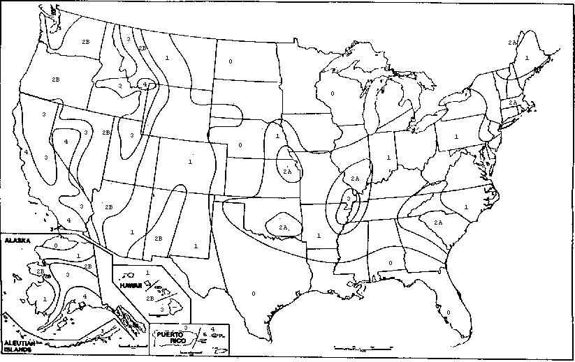
Figure 1 -- SEISMIC ZONE MAP OF THE UNITED STATES
SOME THOUGHTS ON "ADOBE CODES"
By Fred Webster, Ph.D. Seismic Engineer

Email: adobebrix@aol.com   Phone: (650) 321-6939
P.O. Box 4043
Menlo Park, CA 94025
Building codes within the US. are simply agreements among people. Those people with the most representation and technical data to back up their product are listened to the most. Building codes are meant to provide two things:
- A set of regulations for standards of practice on both national and local levels
- A minimum requirement to protect life, at least to a level that is based on currently accepted knowledge.
Unfortunately, by not addressing specific earthen materials and construction techniques, codes restrict the use of these materials and types of construction, even those that may have a long history of success.
Model building codes, such as the Uniform Building Code (UBC), the Basic Building Code (BBC), and the Standard Building Code (SBC), always lag behind current knowledge of materials and construction practices. Within the so called "high tech" building material industries (e.g., steel, concrete, wood, and masonry) the lag time is not significant, with changes being made every two to three years. This is because trade associations (Portland Cement Association, American Institute of Steel Construction, National Forest Products Association, among others) are the main active ingredient in the model code writing process.
It is not the same with earthen building materials. Provisions for the design and construction of adobe structures within the UBC, for example, have not changed significantly since they were first introduced into the code back in the late 1930's or early 1940's. Local "adobe codes", while they are more up to date than the model codes and address more aspects of earthen building practice, are for the most part sorely incomplete and either inconsistent or in opposition to latest knowledge (sometimes rediscovered older knowledge). For example, none of the existing adobe codes" specifically deal with other forms of earthen construction such as rammed earth or pressed block and the special problems specific to their use. Yet these types of construction methods and materials are being used (even within California!) with little or no consistent or appropriate regulation. Without the concerted effort and continued involvement that only an earthen building trade association can bring to bear on the code writing bodies, there is not likely to be any significant change to or continued upgrading of the model and local codes with regard to adobe or other earthen materials.
It is completely understandable that local building officials are loath to take responsibility for materials or construction techniques which are not covered by the building codes and standards. When confronted with these issues, they will more often than not discourage their use or try to force the unknown quantity into the mold of a known one (e.g., requiring rammed earth to conform to Chapter 24 of the UBC), often with inhibitive, inconsistent, and irrational rules. It should further be understood that because of their standardizing Influence, building codes are viewed by lending institutions as a rational and consistent basis for judging the risk in lending mortgage or construction dollars. No wonder it Is difficult to obtain financing for earthen building projects in areas where they are unknown.
In my opinion, all aspects of "adobe codes" are up for scrutiny. So called "traditional practices" of earthen construction which are condoned and sanctioned by many of the present day "adobe codes" in the US are all too often outdated by ignorance of the available information and knowledge, and in many cases are harmful to the earthen building Industry in the long run. In addition, more standards need to be developed for the other materials and types of earthen construction. The earthen building industry needs to stop playing games with code requirements that are meant for other materials and techniques, start compiling and consolidating the available information and data on earthen building and use it to develop rational approaches to design of walls and buildings in seismic zones.
In the discussion that follows, I will point out some of the problems and Inconsistencies that exist within the model and local "adobe codes", as I see them.
Code Seismic Forces
Seismic forces on structures are a fact of life in the US, particularly in the western region. Even In areas where people don't often think of earthquakes such as New Mexico, the historic evidence indicates that earthquakes occur regularly. Ignoring these natural forces in an "adobe code" does not make them go away or make their effects on structures any less destructive. Seismic hazard maps give a vivid picture of the relative activity in different regions. The UBC seismic zone map (Figure 1), for example, is a resource that enables the designer to translate the earthquake hazard into seismic design forces. There are two parts to the seismic requirements within the UBC which must be satisfied by the building design. The first is the minimum lateral force for which the overall structure must be designed, given by the formula:
V= (2.75/Rw)ZIW
where Z is the earthquake intensity factor corresponding to the seismic zone, W Is the total weight of the structure, I is the importance factor for the building occupancy and use, and R. is a force reduction factor related to the inherent ductility in the structure. The second requirement is the minimum lateral force on elements of the structure, given by the formula:
Fp=Z I Cp Wp
where Cp is a horizontal factor given in Table 23-P of the UBC for such things as walls, connections, etc., Wp is the weight of the element The UBC assigns different force reduction factors, Rw to different materials and structural systems (e.g., 12 for special moment resisting frames of steel, 6 for reinforced masonry shear walls). Adobe is inherently a non-ductile material when subjected to shear or tension forces. Unfortunately, there is currently no force reduction factor listed in the code for unreinforced adobe construction, let alone rammed each or other earthen building systems. Indeed, according to the UBC unreinforced adobe is not allowed in seismic zones 2A, 2B, 3, and 4. There Is also no force reduction factor listed in the UBC for reinforced adobe, although some might assume that it falls into the category of reinforced masonry, with Rw = 6. It is suspected that if the code did allow it, the factor for unreinforced adobe in zone 2B" (or any other zone) would be between 1 and 4, with a value of 1 indicating no lateral structural capacity beyond the nominal code design force. A value of 4 indicates a moderate amount of reserve capacity and is probably appropriate for a reinforced earthen building, although this needs to be verified by test. The implications of these numbers are serious, and give us just another warning that we in the earthen building industry need to be more aware of the seismic potential, even in New Mexico. For example, in seismic zone 2B, the required design lateral force using a reduction factor of 4 is 0.14W, or 14 percent of the building weight. But if the appropriate reduction factor for unreinforced adobe is 2, the design lateral force Is 0.28W! This should be compared to the 1985 UBC required lateral force of only seven percent of the building weight, a factor of 4 increase. It is imperative, therefore, that unreinforced adobe be designed the way it has always worked best, with thick walls designed to overcome the effects of earthquake forces.
Some engineers designing earthen buildings in high seismic zones have been tempted to apply strength design concepts, such as those used In the design of reinforced concrete and reinforced fired brick masonry structures, to adobe and rammed earth. In my opinion, this approach is not appropriate for earthen structures because the two main assumptions upon which strength design is based do not apply to this material. Earthen walls cannot bond with conventional rebar in order to stretch them to their yield stress. Thus, assumptions concerning the ultimate behavior of earthen walls based on yielding of steel reinforcement are likely not to be accurate. It is also recognized that the compressive strain levels achieved in reinforced masonry are less than those in reinforced concrete, and it is likely that the ultimate strain levels in adobe and rammed each are even less thus making the use of UBC provided material understrength factors for concrete and masonry inappropriate. Much testing would need to be completed before strength design concepts could be applied to earthen building materials.
Wall Heights and Height-to-Thickness Ratios
Some rather arbitrary limits on minimum wall thicknesses and height-to-thickness rations for both laterally unsupported and laterally supported unreinforced adobe walls are stated in existing "adobe codes." Several codes, including the UBC, specify that for laterally unsupported walk the h/t ratio cannot be more than 10. For laterally supported walls, the New Mexico State Adobe Code and other local "adobe codes. allow exterior walls to be 10 inches for single story buildings and 14 inches for the first story of a two story building they also allow interior walls, laterally supported, to be a minimum of 8 Inches. There is no specified h/t limitation for such walls. These height limits are meant for all areas of New Mexico, including seismic zone 2B. Not that the UBC specifies a minimum wall thickness of 16 inches for all adobe bearing walls in seismic zones 0 and 1, and does not even allow unreinforced adobe to be constructed in zones 2A and higher. Examples of cities in zone 2B include Albuquerque, Silver City (NM), Flagstaff (AZ) and Las Vegas (NV).
Local tradition In some cases results in an irrational rule in "adobe codes." For example, the variance in the New Mexico Adobe Code which allows the stem wall to be two inches thinner than the thickness of the adobe wall it supports (perimeter insulation not withstanding) is not structurally sound with regard to the seismic resistance of the wall. The variance effectively reduces the lateral had residing wall thickness from 10 inches to 8 Inches, while leaving the wall mass, and consequently the inertia forces caused by the earthquake, equal to that of a 10-inch wall.
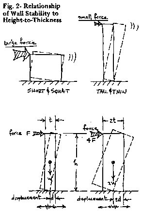
For limits on thickness to provide adequate safety, there must be limitations on the height as well. The concept of safe limitations on wall height-to-thickness ratios is not magic. It is easy to see that a short squat block is harder to push over than a tall thin one (see Figure 2). In the second example illustrated in Figure 2, one wall is twice as thick as the other, while the heights are the same. However, it takes four times as much force to start to tip the thicker wall and twice as much horizontal ground displacement during the shaking to actually tip it over. Although the true structural behavior of walls during earthquake ground motion is not quite as simplistic as illustrated in Figure 2, the basic concept is a valid rule of thumb for both walls and other vertical building elements such as columns.
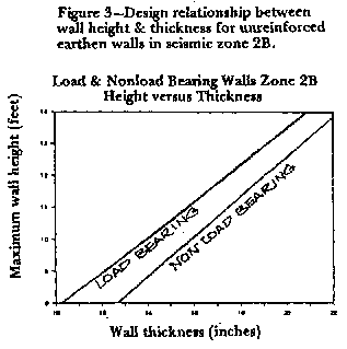
There should also be a distinction between load bearing and non-load bearing walls. It is clear from a rational engineering analysis of wall thickness versus wall height that the wall thicknesses stated In the New Mexico State Adobe Code are unconservative for UBC seismic zone 2B (see Figure 3). As an example, according to the height-to-thickness relationship shown in Figure 3, an unreinforced non-load bearing interior wall 8 feet tall in zone 2B should be at least 12-1/2 inches, not 8 inches as allowed by the New Mexico Code. For an unreinforced load bearing wall 9 feet tall, the thickness should be 12 inches, not 10 inches. The New Mexico Code was unconservative for previous versions of the UBC as well, but it is now even more so since the design lateral earthquake force has increased by 33 percent.
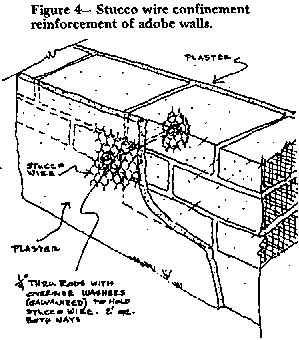
It should also be pointed out that even rational engineering analyses of unreinforced earthen walls using conventional engineering principles do not tell the whole story of how an earthen structure will perform during an earthquake, particularly since we know that earthquake records always indicate forces greater than those predicted by the building code. To better understand the consequences of constructing walls or columns with various height-to-thickness ratios, it is necessary to study the behavior of existing earthen buildings during severe seismic shaking and/or the behavior of test walls on the shake table. Studies of historic adobe structures that have performed well through major earthquakes as well as shake table tests, indicate that it is wise to design walls with a hit ratio of 5 or 6, not 10. A ratio of 10 or greater is really a candidate for reinforcement of the walls in order to confine the earthen material (see figure 4), because it will break up or blow out during a significant shake.
Code Requirements for Reinforcement
One of the major points of contention within the earthen building industry is the requirement for arbitrary amounts of reinforcement in seismic zones. The UBC has a requirement for minimum reinforcement of masonry walls in seismic zones 2A, 2B, 3, and 4 which have been interpreted by building officials in various communities as being applicable to adobe and rammed earth alike. From the UBC point of view, these seismic zones cover about one third the area of New Mexico, half of Arizona, three quarters of Utah, and all of Nevada and California (see Figure 1 for the Seismic Zone map of the US).
For zones 2A and 2B, the UBC calls for a minimum of one #4 vertical bar at all building corners and the sides of all windows and doors, and also a minimum of #4 vertical bars spaced no more than four feet on center along the length of the walls. In the horizontal direction, the UBC requires a #4 bar at the top and bottom of all openings, at the top and bottom of all walls, and at any intermediate floor levels (see Figure 5).
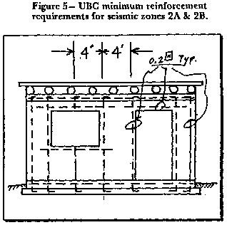
These minimum requirements are arbitrary, but are meant to produce ductile-type action under earthquake loading. The underlying principle is that the steel will yield and hold the masonry together. However, at such large intervals steel placed in adobe or rammed earth walls will not prevent the earthen material from falling out of the wall if it breaks up during severe ground shaking. It is also thought that placing vertical bars at such large intervals creates weak points in the wall and high stress concentrations at these points causing more problems than if there were no reinforcement. However, to my knowledge, this hypothesis has never been proven by test or through observed earthquake damage.
Reinforcement in adobe has always been viewed as impracticable, particularly vertical reinforcement, due to the size and arrangement of the blocks, as well as the fact that adobe with mud mortar does not grab onto or bond with steel reinforcement the same way that fired brick or concrete block masonry with cement-based mortar does. Reinforcement does not bond to the adobe unless it is embedded in a cement-based mortar and grout or unless there is a positive interlacing of reinforcement around the earthen material, such as the case of using ladder reinforcement or welded wire fabric. Placing vertical steel reinforcement in adobe walls can be difficult particularly if the wall is only one block thick. It either requires making a special block with pre-formed holes, or drilling from the top down through the wall after the wall is complete.
Placing reinforcement in a rammed earth wall is somewhat problematic because not only is it awkward to physically maneuver with the tamper around the rebar and within the confines of the forms, the ramming process cannot produce the adequate compaction around the vertical or horizontal bars. Thus, bonding of the soil (even a soil-cement mixture) to the rebar does not occur. The fact that the steel reinforcement does not bond with the earthen wall material negates the legitimacy of any stress calculations performed by the engineer or designer.
As if seismic zones 2A and 2B reinforcement requirements were not difficult enough to comply with, in zones 3 and 4 the UBC calls for a minimum percentage of steel in both horizontal and vertical directions, the absolute amount of this required steel thus being in direct proportion to the thickness of the walls. The UBC requires a minimum reinforcement in the vertical and horizontal directions of not less than 0.0007 times the gross cross-sectional area of the wall, and the minimum sum of the horizontal and vertical reinforcement not to be less than 0.002 times the gross cross-sectional area of the wail. Again, these requirements are arbitrary and are not based on need, as might be indicated by an engineering analysis. They are meant to provide ductile-type behavior in the structure and assist in crack control. On the contrary, it should be understood that placing heavy steel reinforcement in earthen walls actually creates cracking in the walls as the earthen material continues to shrink during the drying process over a long period of time and the unyielding steel tries to hold it from shrinking, thus creating tension stresses that the earthen material cannot sustain.
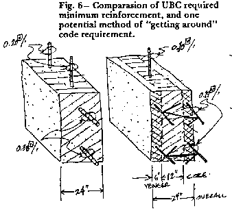
The absurdity of this minimum reinforcement requirement when applied to massive earthen walls in seismic zones 3 and 4 is underscored by the fact that the earthquake stresses in an unreinforced wall decrease with thickness, while at the same time the UBC provision for a wall 24 inches thick requires two times as much steel as a wall 12- inches thick! Applying this criterion to a 24-inch rammed earth wall results in a need to provide 0.20 square Inches of vertical rebar In every foot of wall length and 0.38 square inches of horizontal rebar in every foot of wall height, or vise versa. This means one #4 bar every foot, one #6 bar every two feet, or one #8 bar every four feet in one direction, while it means one #6 bare every foot, one #8 bar every two feet, or one #11 bar (nearly 1-1/2 inches in diameter) every four feet in the other direction!
To get around this dilemma, some builders resort to designing their walls as though they consisted of a core thickness of say 12 inches with an inner and outer layer of veneer, six inches thick, on either side of the core (see Figure 6). In other words, it is assumed that only the center 12 inches of the rammed each wall is structural and that the outer six-inch layers are non-structural veneers. In this way the required minimum steel is cut in half, but it also requires veneer anchor ties to be designed in accordance with Chapter 30 of the UBC. Using ladder-type reinforcement placed horizontally, however, takes care of the anchor tie requirement.
Although they are not recognized in any existing building code, there are other methods of providing adobe masonry and rammed each with ductility that do not require internal reinforcing with steel. One such method, which has been tested on the shake table, uses externally applied welded wire fabric or stucco netting to contain the earthen walls when they began to crack badly and break into smaller chunks during severe lateral shaking These tests showed the value of containment reinforcement as opposed to strength reinforcement
Bond Beams
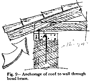
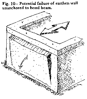
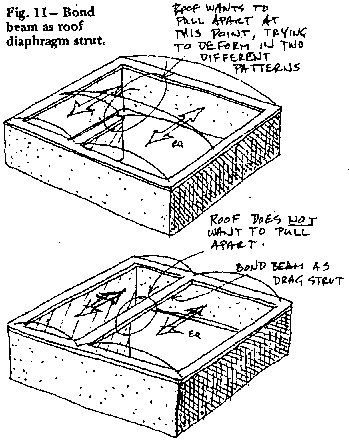
One of the most important structural elements for resisting earthquake forces in an earthen building (as well as wind and gravity forces) is the bond beam. Yet not enough attention is paid to this element in "adobe codes" or in design. Bond beams accomplish several purposes: they distribute concentrated roof loads to the bearing walls (Figure 7); they distribute lateral inertia forces from the roof mass into the load and non load bearing walls (Figure 8); they provide an anchor to the roof for wind loads (Figure 9); they keep the walls from slipping out and falling over during lateral shaking (Figure 10); they can also act as drag struts to carry roof inertia forces to shear walls which are discontinuous (Figure 11)
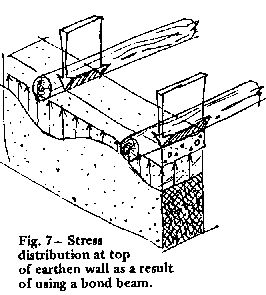
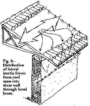
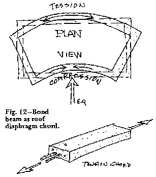
Regarding the transfer of lateral inertia loads from the roof mass to the walls, there are two basic engineering design approaches to this problem: construct a diaphragm, in which the bond beam is designed as the chord element (see Figure 12); or construct an independent beam with no roof diaphragm (see Figure 13). The designs for these two fundamental approaches are different. In the first case, the bond beam steel is placed near the center of the cross section and is required only to carry tension forces in conjunction with the diaphragm action of the roof. In the second case, the bond beam must have reinforcement placed in the two faces In order to resist bending from both the inward and outward inertia forces, while the roof does not act as a diaphragm.
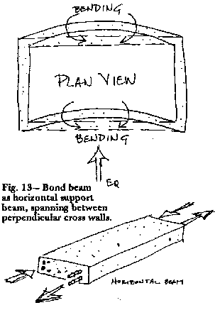
Some basic information about bond beams that should be somehow reflected in the "adobe codes". include:
- Bond beams should be continuous.
- They should be stiff and strong in the direction perpendicular to the plane of the wall (i.e., full, or near full width of the wall thickness with rebar in both faces if designed as a beam to carry lateral forces).
- They should restrain the out-of-plane deflection of the wall as much as possible, although, if they hinge at the comers of the building, rather than the resisting bending moment, this is all right.
- In the up and down direction, bond beams should be flexible but strong (i.e., no more than 5 or 6 inches in depth, with rebar at mid depth). Note that this important concept is new and is the direct consequence of observations made of shake table tests on adobe structures.
- Bond beams should be positively anchored to the tops of the walls to prevent the walls from slipping out from underneath them during lateral shaking and to provide anchorage against uplift from wind.
- Anchor rods should be closely spaced (i.e., 12 to 24 inches) to eliminate stress concentrations from lateral forces or uplift.
Rammed Earth
One of the main concerns I have heard from building officials regarding rammed earth is quality control of the finished rammed wall. It is one thing to maintain a uniform quality in the mix proportions by making up test cylinders from the day pile. It is altogether a different matter to maintain the same level of quality control in the finished wall, since this method of construction relies to the extreme on the quality of workmanship. One way of obtaining the needed quality control information is to require that cores be taken from the finished wall and tested for compressive strength. However, this is not only expensive, but it is also destructive to the wall. Other less expensive and less destructive methods of obtaining this information need to be developed. One potentially viable test recently brought to my attention was a test for soil compaction, such as may be performed with a nuclear density gauge (ASTM #D2922-81 method B) or other means. If compaction within the wall can be correlated with compressive strength, it would negate the need for coring. At the present time such compaction testing procedures are not specifically written for rammed earth walls, but it should certainly be possible to adapt one or more of the existing procedures to the purpose by trial and error and with initiative from and cooperation within the rammed earth industry. A rammed earth quality control test standard should be developed
Pressed Block
Standards for pressed earth blocks are not addressed in any of the "adobe codes." Pressed block differs from adobe In the fact that it relies on externally applied pressure for compaction and bonding of clay and sand particles, whereas adobe relies on electro-magnetic bonding of the clay particles and water so that during the drying process the clay particles are drawn together tightly for strength. The quality control of adobe block is reasonably well known, since the manufacturing process has been around for thousands of years. Pressed block technology, comparatively, is in its infancy. Manufacturers of pressed block have focused on increased compressive strength as the standard by which to judge the quality of their product, while disregarding the type of soil used, sometimes with disastrous consequences. In actuality, high compressive strength is and should not be the greatest concern related to pressed block quality. If the block has a compressive strength of 1000 psi rather than 300 psi, it is quite superfluous to the performance of the building subjected to ordinary service loads or even earthquake loads. It is not requisite that earthen blocks be up to the standard of concrete in order to perform well during severe earthquake shaking. However, if the blocks are manufactured from soils with expansive clays, there is a significant chance that the walls will disintegrate after a period of time, particularly if they are subjected wet-dry cycles. Standards for appropriate soil selection need to be aggressively and rationally developed and tested by the pressed block industry. Currently, the best standards and research are being performed by BASIN, a combined appropriate technology effort made up of Germany, England, Switzerland, and France.
Plaster
It is well known within the conservation community that historically the use of Portland Cement plaster often does more harm than good in attempting to act as a barrier to water intrusion into earthen walls, and yet most of the "adobe codes" that allow construction with unstabilized adobe block call for exterior walls to be plastered with 3/4" of Portland Cement plaster in accordance with Chapter 47 of the UBC. This type of unquestioned acceptance of existing code provisions for use with adobe and other earthen materials is the very thing that the earnhen building Industry must resist. Instead of accepting the expedient solution offered by the code for other applications decisions regarding appropriate aspects of an "adobe code" should be made based on the experiences of the past (even the historical past) and the best information available.
Mortar Head Joints
Some of the "adobe codes" address mortar bedding and head joints. For example, the New Mexico Adobe Code states that bedding joints shall be "full flush," but that the head pints may be left partially open to allow for plaster application it is my opinion that such discontinuities in the masonry wall are not a good idea for the seismic resistance of the wall. Tests performed in Peru and Mexico have shown quite clearly that the quality of workmanship in construction gives an inappropriate signal to the adobe construction Industry that it is all right to allow, what effectively would be poor. workmanship. The seismic strength of walls should not be sacrificed for the sake of providing a convenience to the wall plasterer.
Wrap-up
It is apparent that earthbuilders in seismic zones 2A and 2B should encourage thicker walls, better bond beam attachments to those walls and consistent rational standards for adobe, rammed earth, and pressed block. To the contractor who has a minimal system "down," which gets permitted and built and makes him a good profit, such changes may seem threatening. However, the increased thermal and aesthetic benefits and the idea that a structure may honestly be advertised as "seismically resistant will certainly draw out the caliber of client who appreciates such quality in a custom home.

 Debian Linux